Injection molding is the most widely used process for producing plastic parts — yet even experienced manufacturers face recurring issues that affect quality, efficiency, and cost. In this article, we’ll look at four of the most common real-world problems and share practical solutions and design tips that you can apply immediately to improve your production.
Issue One: Defects of Sink Marks, Warpage, and Flow Lines
The Issue that Costs You Most
If you spent enough time on an injection molding production floor, you know the feeling. You open the mold after a cycle, expecting a perfect part, and instead, you find a warped, flawed component that’s destined for the scrap bin.
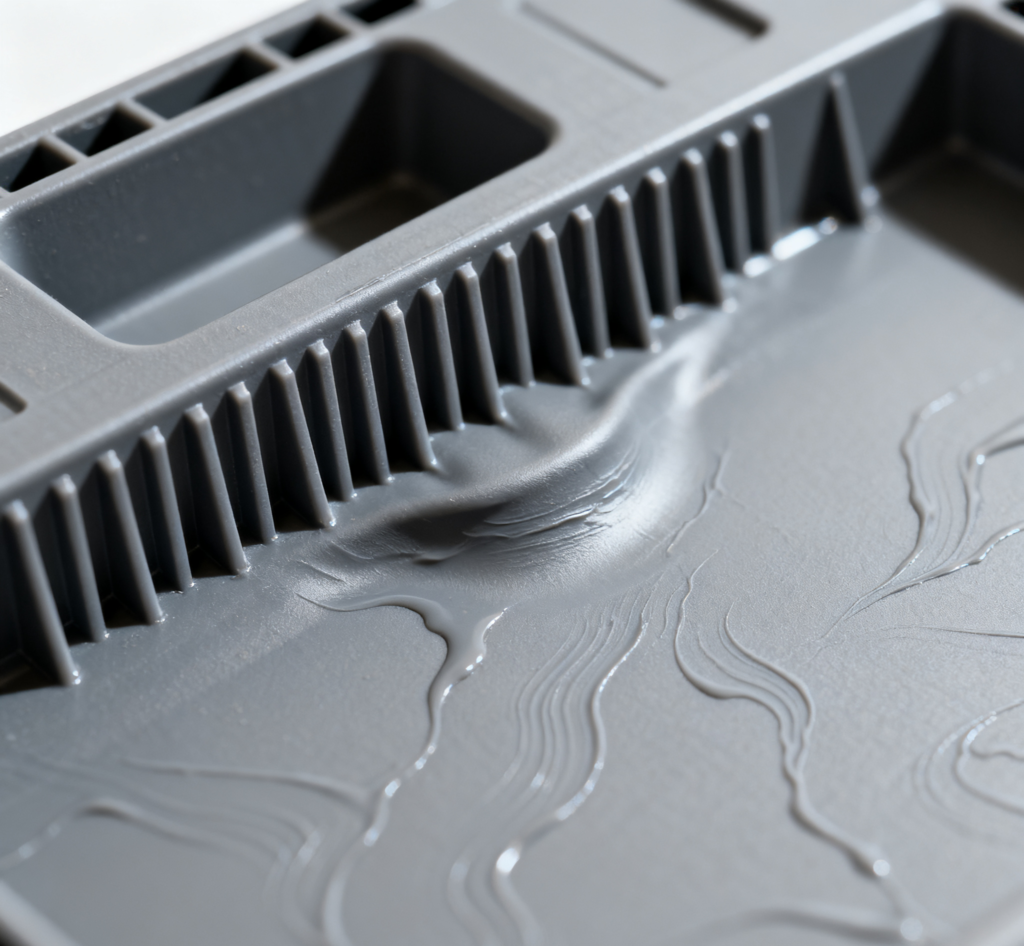
The three defects are among the top reasons for part rejection. A 2022 industry survey showed that over 40% of injection molding quality complaints were related to these defects. They not only hurt aesthetics but can also compromise structural integrity.
Why They Happen:
- Non-uniform wall thickness causes uneven cooling and shrinkage.
- Sharp internal corners concentrate stress, making warpage worse.
- Inadequate packing pressure leads to incomplete material compensation during cooling.
The Engineering Solutions
Maintain Uniform Wall Thickness
This is the #1 rule. Thick sections cool more slowly than thin ones, pulling material inward and causing sinks. Aim for consistent wall thickness throughout the part, as a rule of thumb, keep variations under ±20%.
If you must have a thicker feature (like a rib or boss), make it no more than 60% of the nominal wall thickness.
Round Those Internal Corners
This process can distribute stress and improve flow, and here is how:
- Replace sharp internal corners with radii of at least 0.5 x the wall thickness
- This reduces stress concentration by up to 40%
- Prevents sink marks at corner junctions
Optimize Process Parameters
- Increase packing pressure gradually: start at 80% of the injection pressure
- Extend packing time to 120-150% of gate freeze time
- Reduce melt temperature by 10-15°C to minimize shrinkage differential.
This three-step approach forms a highly effective strategy for combating shrinkage and warpage. But it’s critical to remember that these values are interdependent starting points, not fixed rules; the optimal settings for pressure, time, and temperature must be validated through careful DOE to establish a robust, economical process window for your specific material, mold, and part geometry.
Issue Two: Gate Location and Hot-Runner Design
The Hidden Bottleneck in Your Mold
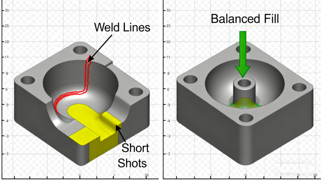
Poor gate placement can result in uneven filling, visible weld lines, or short shots. Cold runner systems, while cheaper, generate excessive scrap and increase cycle time.
Some Golden Rules for Gate Position:
Gate at the thickest section
This allows for better control of packing and shrinkage, directing the sink mark to a less critical area (like the inside of a housing) and ensuring the cavity fills completely.
Consider flow length ratios
Keep the L/t (length to thickness) ratio under 150:1 for most materials, but the value depends on the material’s flow properties.
Avoid gating into thin walls
To prevent jetting and flow marks.
Beyond these, a successful design must proactively control the location and quality of weld/meld lines, facilitate venting to avoid air traps, minimize molecular orientation to reduce internal stress and warpage, and finally, consider the aesthetic and finishing implications of the gate vestige. Ultimately, leveraging Moldflow simulation is the most powerful method to validate these decisions, balance the competing priorities, and prevent costly mold reworks before steel is cut.
The Benefits of Hot-runner Design
- Material savings: 15-25% reduction in overall material usage
- Cycle time reduction: 10-20% faster cycles (no runner cooling required)
- Quality improvement: 60% reduction in weld line defects
- ROI timeline: typically 12-18 months for volumes over 100K parts/year
Conclusively, for high-volume jobs, a hot-runner system keeps the material molten in the manifold, eliminating sprue and runner scrap. This can reduce material waste, improve consistency, and allow for faster cycling.
Issue Three: Cooling System Optimization and Cycle Time Reduction
The 70% Factor Most Engineers Ignore
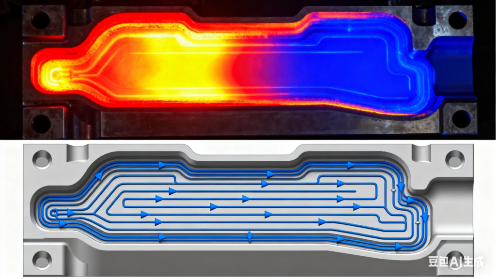
Cooling accounts for 60–70% of the total molding cycle time, making it the biggest bottleneck in production. Poorly designed cooling channels lead to hot spots, longer cycles, and inconsistent part dimensions.
Some Optimized Cooling Strategies
Optimize Cooling Channel Layout
Standard drilled cooling lines are often too far from the part surface. Work with your mold maker to design channels that follow the contour of the part as closely as possible for uniform heat extraction. The following proven parameters are provided for reference.
- Distance from part surface: 1.5-2.0 times channel diameter
- Channel spacing: 3-5 times channel diameter
- Inlet/outlet temperature differential: maintain under 3°C
- Channel diameter: 8-12mm for most applications
Consider Advanced Solutions
For the most challenging parts (with deep cores or thick sections), investigate conformal cooling (3D-printed channels that perfectly hug the mold geometry) or high-conductivity mold materials like copper alloys.
Conformal Cooling ROI– Conformal cooling (following part contours) provides:
- 25-40% reduction in cooling time
- 15-20% improvement in part quality consistency
- 60% reduction in warpage on complex geometries
Implement Precise Mold Temperature Control
A dedicated mold temp controller isn’t a luxury; it’s a necessity. It ensures consistent part quality from the first shot to the millionth.
Here are some Temperature Control Best Practices:
- Use separate temperature controllers for different mold zones
- Maintain mold temperature within ±2°C for consistent quality
- Consider rapid temperature cycling for improved surface finish
Issue Four: Threaded Inserts and Snap-Fit Design
Assembly Nightmares and How to Avoid Them
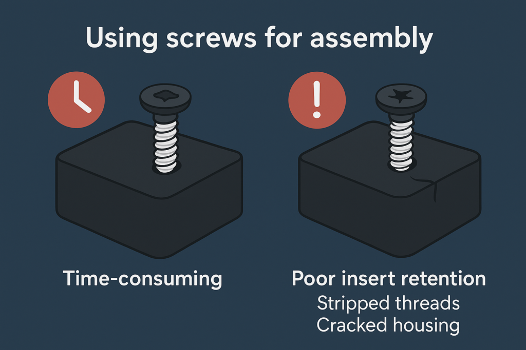
The molding was perfect, but the product failed in the customer’s hands. Stripped threads from self-tapping screws and broken snap-fits are a nightmare that leads to warranty claims and brand damage.
Poor fastening design is the leading cause of field failures in assembled plastic products. We found that almost 45% of them involved fastener-related failures: stripped threads, cracked bosses, or broken snap-fits.
How to Improve?
Use the Right Inserts
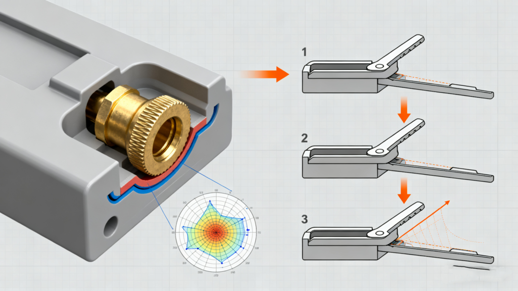
For any thread that will withstand more than a few assembly cycles, use a brass or stainless steel threaded insert. Ensure they have proper retention features—knurling for light duties, undercuts for higher pull-out strength. For the strongest bond, specify ultrasonic or thermal installation.
Threaded Insert Selection Advice
- Brass inserts: Best for low-stress applications, easy installation
- Stainless steel: High strength, corrosion resistance for outdoor use
- Heat-stake inserts: 40% faster installation than press-fit types
Critical Design Parameters for Boss
- Boss outer diameter: 2.0-2.4 times insert diameter
- Boss height: 0.8-1.2 times insert length
- Wall thickness around boss: minimum 1.5mm for structural integrity
Improve Snap-Fit Design
A well-designed snap-fit is faster, cheaper, and more reliable than a screw. Follow the principles of allowing sufficient deflection and keeping strain levels below the material’s maximum (typically below 70% of its yield strain for PP, for example).
Design Guidelines
- Cantilever beam deflection: limit to 30% of the material’s ultimate strain
- Stress concentration factors: use generous radii (R ≥ 0.5mm minimum)
- Engagement force: 10-25N for manual assembly, 25-50N for automated
The advantages of optimized snap-fit
Properly designed snap-fits can replace 60-80% of threaded fasteners, and reduce:
- Assembly time by 30-50%
- The materials cost of the eliminated fastener
- Assembly complexity and potential for errors
Conclusion: Your Action Plan for Better Injection Molding
These four focus areas – part quality through design, intelligent gate placement, cooling optimization, and smart assembly features – form the foundation of successful injection molding operations.
In XDL, we excel in these areas and consistently achieve:
- Rejection rates under 1%
- 15-25% shorter cycle times
- 20-30% lower total production costs
- 90%+ on-time delivery performance
Start with the biggest impact
If you’re currently experiencing high rejection rates, tackle defect prevention first. For high-volume products with acceptable quality, cooling optimization typically provides the fastest ROI.
Take Action Today
What injection molding challenges are keeping you up at night? Share your specific situations in the comments below – Or you can contact our expert in the injection molding field, discussing the solutions together!
—————————————————————————————————————————–
Download our free “Injection Molding Design Checklist” to catch common mistakes before they cost you time and money.